Stacking Fault
Simulations – II
Introduction: In this exercise and the next you will simulate some diffraction patterns from kaolinite clays. Kaolinite, Al2Si2O5(OH)4, is a 1:1 layer silicate with a single unique sheet with AlO6 octahedra on one side and SiO4 tetrahedra on the other. The layers stack with an offset to ideally form a triclinic C1 lattice (Bish & Von Dreele, 1989, Clay & Clay Min. 37, 289-296) for a sample of the most ordered form of kaolinite from Keokuk, Iowa. Kaolinites from other locations evidently have stacking faults so that the peaks are displaced, have peculiar shapes and are above a varying background. For the exercise we provide a laboratory Bragg-Brentano pattern of Keokuk kaolinite collected with CuKa radiation on a Bruker instrument and thus in the Bruker RAW file format. The Keokuk kaolinite has some dickite (different ordered stacking of kaolinite layers). The next exercise Stacking Faults-III) covers a simple simulation of a faulted kaolinite from Georgia.
If you have not done so already, start GSAS-II.
Part 1. Creating
kaolinite layer
In this initial step we will load from a cif file the structure of kaolinite, draw it to see the layer structure and then transform it into forms suitable for stacking simulations. To begin do Import/Phase/from CIF file; from the file dialog select StackingFaults-II/data/kaolinite.cif. After the “are you sure” popup, there will be another warning you that 4 atom types (‘O-H’) were not recognized chemical element symbols and they were substituted by Xe to make them obvious in the atom list. Press Ok; you are offered a chance to change the phase name, I used ‘kaolinite’. The General tab is displayed (notice the presence of Xe in the element table).
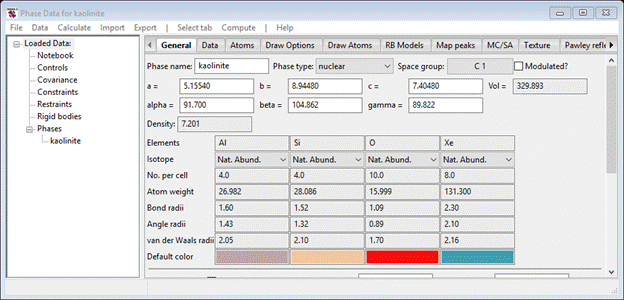
To fix the Xe atoms (they should be O), select Atoms and then double click the Type column heading; a small popup will appear. Select Xe & press Ok; the Xe atoms at the bottom of the atom table will be highlighted. Next select Edit Atoms/On selected atoms…/Modify parameters from the Phase Data menu; a new popup will appear. Select Type & press Ok; a periodic table of the element will appear. Select O from the O-atom pulldown; the structure will be drawn with Al, Si & O atoms only.

To better visualize the stacking layer, select the Draw Atoms tab and then double click the empty upper left corner box of the table. All atoms will turn green. Then do Edit Figure/Fill unit cell; the structure will be redrawn with all atoms that belong in the unit cell. Finally, double click on the Type column heading, select Al & Si (they will turn green) and then do Edit Figure/Fill CN sphere. After a bit of rotating the structure around, the layering along the c-axis (blue line) will be evident.

One can easily see the layer of SiO4 tetrahedra and AlO6 octahedra. Also notice that the next layer (represented by the 4 O atoms at the bottom of the above drawing are offset giving a triclinic lattice.
The stacking fault simulation calculation via DIFFaX routines requires that the stacking layers be defined in a coordinate system that has the stacking direction perpendicular to the stacking plane defined as the c-axis. This requires transformation of the unit cell and atom coordinates; a suitable tool exists in GSAS-II to do this. Select the General tab and do Compute/Transform; a popup window will appear.

Note that this allows one to transform the structure according to a matrix and then shift the resultant positions along some vector and then select those that are unique according to a selected space group. The pulldown gives a selection of commonly used transformations; we want the last one, abc*, which satisfies the stacking fault requirement. Select it; notice that the space group is changed to P1. Leave this as the kaolinite layer has no symmetry; in other circumstances the layer may have an inversion center in which case P-1 should be used. If you press Test, the new lattice parameters will be shown.

The a & b axes stay the same, but c is now smaller (the interlayer distance in kaolinite) and a & b = 90 (g is unchanged). Press Ok; a new phase (kaolinite abc*) will be made and its General tab will be shown immediately. Select the Draw Atoms tab to see the resulting structure.

To see what this layer looks like with more of it drawn, you can add more unit cells to the drawing; select all the atoms by double clicking the upper left empty box of the Draw atoms table. Do Edit Figure/Add atoms and increment the 1st Choose unit cell and press Ok; this will add one unit cell along x. Now select all the atoms again, do Edit Figure/Add atoms and now decrement the 1st Choose unit cell. Press Ok; the drawing will now be 3 unit cells wide along x. Repeat this once more decrementing the 2nd Choose unit cell to give a 3x2 unit cell block of atoms. Double click the Style column heading and select Balls and sticks; the drawing should look like (after some zooming/shifting/rotation).

This structure is now suitable for use in DIFFaX calculations; the cell has a c-axis that is perpendicular to the ab plane with a length that is the stacking repeat distance. This is a good place to save your project (I called it ‘kaolinite’).
Part 2. Set up
simulation of ideal kaolinite stacking
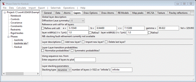
In this part of the tutorial we’ll create a stacking model for Keokuk kaolinite and use DIFFaX to simulate the powder pattern and compare it to some real data. To begin we need a new phase that we can declare as “faulted’. In the main GSAS-II data tree menu do Data/Add new phase; I named it ‘Keokuk’. The General tab for it will immediately appear.

Change the Phase type to ‘faulted’; the General tab will be redrawn and a new tab ‘Layers’ will appear. Select it.

We can anticipate (given that kaolinite space group is C1) that the Diffraction Laue symmetry is -1. We can enter by hand the lattice parameters from the kaolinite abc* phase but an easier method is available. Do Operations/Copy phase cell; a file selection dialog will appear for your current directory and the file kaolinite.gpx should be there. Select it; a small popup will appear listing the available phases. Choose ‘kaolinite abc*’ and press Ok; the Layers window will be redrawn with the new lattice parameters.
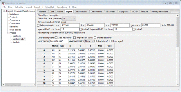
Next, you need to define the layer. As it would be very tedious to enter 24 atoms by hand, the alternative is to get them from the previously created kaolinite abc* phase. Select the Import new layer box; the file dialog with kaolinite.gpx will appear. Select the file and press Open; again a small popup with two phases listed will appear. Again select kaolinite abc* and press Ok; the Layers page will be redrawn with a layer (named kaolinite) will be filled out.
If you move down to the bottom of the page to find the one line Layer-Layer Transition probabilities. Change Dz=1.0 and press the plot box; the drawing will show a layer of kaolinite stacked directly above another one.
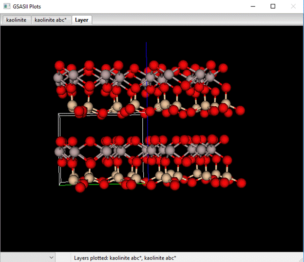
Compare that to the stacking in kaolinite.

Notice the effect of the offset. The 1st row of SiO4 tetrahedra are positioned directly above the AlO6 octahedra in the real structure but not in the vertically stacked structure. We can use a bit of simple geometry to work out what the offset is but first let us see what happens in the simulation and how it compares to real data.
Step 3. Import
Keokuk kaolinite data and do 1st simulation
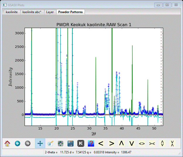
First we need to import the Keokuk kaolinite powder data; do Import/Powder Data/from Bruker RAW file. Select Keokuk kaolinite.RAW from the file dialog box; press Yes in the next popup. A new file dialog appears requesting an instrument parameter file; we will use an internal default instead. Press Cancel and select Defaults for CuKa lab data from the next popup. This process will repeat since the RAW file contains two scans. In the next popup, select only Keokuk (3rd phase). There will be two PWDR scans in the GSAS-II data tree; one covers 2Q= 10-90° and the other covers 2Q=80-150°. Only the lower part of the first one is going to be used in our simulation work as the calculations become very time consuming for complex structures and high angle data. Select PWDR Keokuk kaolinite.RAW Scan 1 from the GSAS-II data tree make sure it expands; its plot will also show.

Go to Limits and set Tmax to 52.0; that puts the upper limit in a relatively clear part of the pattern. Then go to Background and set the 1st coefficient to 20 (approximately the background at 2Q=18). Next go to Sample parameters and set the Histogram scale to something reasonable (I chose 20.0) and make sure the Diffractometer type is Bragg-Brentano.
Now we are ready for our 1st kaolinite simulation. Go to Phases/Keokuk and select the Layers tab. Do Operations/Simulate pattern and press Ok in the popup. Select the Scan 1 pattern and press Ok; the simulation will finish quickly (press Ok) and the new plot will be displayed (I’ve zoomed in a bit).
 .
.
As you can see the simulation (green curve) does not fit the data (blue crosses) at all mostly due to the incorrect layer offset although the 1st peak seems to be positioned correctly. To work out the offset consider the drawing of kaolinite.

The offset Dx is given by the blue arrow in the above
drawing of kaolinite and is in fractional coordinates. Geometry gives
![]() Or
in this case -0.368.
Set Dx to this
value & repeat simulation.
Or
in this case -0.368.
Set Dx to this
value & repeat simulation.

There is some improvement but some parts are not very well represented. Recall from the triclinic kaolinite lattice parameters that a was 91.7°; that will produce a small offset in Dy. Using the same kind of geometry math gives Dy=-0.0246. Enter this value & repeat the simulation again. This gives a much better fit to the observed pattern, but the simulated peaks are too sharp; this can be fixed by changing the U,V,W Instrument parameters. I’d just set W=40 and the Histogram scale (in Sample parameters) to 40 and try again.
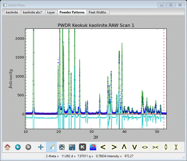
That is a pretty good fit for a stacking simulation. By
further hand tweaking of the parameters one can further improve the simulation
but based on what we see here we do have the right description of stacking in
Keokuk kaolinite. Doing sequence simulations varying each parameter over a
small range can be used to help with optimization, but in this case it would be
far easier to do a Rietveld refinement for this well ordered kaolinite. Save
your project as you will need it for the next exercise (Stacking Faults-III).